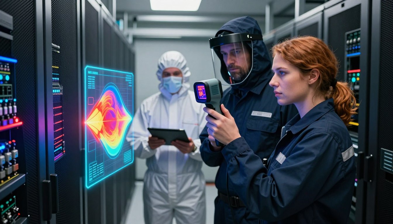
Most electrical failures announce themselves with heat long before they cause an outage or a fire. Loose connections, corroded terminations, unbalanced loads, and failing components all raise temperature. Infrared thermography makes that heat visible without contact and, when performed correctly, without interrupting service. It is one of the most cost-effective tools in an electrical predictive maintenance program.
The Physics in Brief
Every object above absolute zero emits infrared radiation. A thermal imager measures that radiation and converts it into an apparent temperature. The conversion depends on several factors the thermographer must understand and control:
- Emissivity: how efficiently a surface emits infrared energy. Painted and oxidized surfaces typically have high emissivity. Bare, polished metals such as copper bus or aluminum lugs have low emissivity and can appear deceptively cool.
- Reflected apparent temperature: low-emissivity surfaces reflect radiation from nearby sources, including lights, people, and other equipment.
- Distance and spot size: small targets viewed from too far away are averaged with their background, understating the true temperature.
- Atmosphere and windows: transmission losses through air, viewing windows, or protective covers must be accounted for.
Thermography is therefore a measurement discipline, not point-and-shoot photography.
Thermographers also distinguish between qualitative and quantitative inspection. Qualitative work identifies thermal patterns and anomalies by comparison. Quantitative work assigns reliable temperature values, which requires careful control of emissivity, reflected temperature, and distance. Most electrical programs rely on qualitative comparison supported by quantitative measurement where severity decisions depend on it.
Planning an Effective Survey
A successful inspection begins before the camera is switched on. ASTM E1934, Standard Guide for Examining Electrical and Mechanical Equipment with Infrared Thermography, provides a useful framework for planning, performing, and documenting inspections. Key planning steps include:
- Build a prioritized equipment list based on criticality and failure history.
- Schedule inspections when equipment is under representative load; many programs aim for at least 40 percent of rated load where practical.
- Coordinate with operations so covers can be removed or infrared windows accessed safely.
- Prepare the arc flash risk assessment and PPE requirements for each location.
- Establish baseline images for comparison in future surveys.
NFPA 70B, Standard for Electrical Equipment Maintenance, became a standard rather than a recommended practice in its 2023 edition. It addresses thermography as part of an electrical maintenance program and is an important reference when setting inspection frequency.
Safety Comes First
Opening equipment covers to obtain a clear line of sight can expose the thermographer to shock and arc flash hazards. Removing covers is itself a task that requires an NFPA 70E risk assessment. Infrared windows and viewing ports, installed during planned outages, can reduce exposure by allowing inspection with covers closed. Where covers must be removed, only qualified persons wearing appropriate PPE should do so, and the thermographer should remain outside the arc flash boundary whenever possible.
Interpreting Results and Assigning Priority
The most common approach compares temperatures between similar components under similar load, such as the three phases of a feeder, or compares a component to ambient air. The ANSI/NETA Maintenance Testing Specifications provide widely used temperature-difference criteria for assigning priority. A typical program uses tiers like these:
| Priority | Typical meaning | Typical action |
|---|---|---|
| Low | Minor difference, possible deficiency | Investigate at next scheduled maintenance |
| Intermediate | Probable deficiency | Repair as time permits |
| Serious | Significant deficiency | Monitor and schedule repair promptly |
| Critical | Major discrepancy | Repair immediately |
Apply the specific thresholds from the edition your organization has adopted, and always interpret findings with load, emissivity, and component design in mind.
Some patterns deserve particular caution. A hot spot at a connection usually points to high resistance from looseness, corrosion, or undersized hardware. A uniformly warm conductor suggests overload or harmonic heating. A cooler-than-expected phase can indicate an open circuit or a failed component. Fuses, breakers, and transformers each have characteristic thermal signatures that trained thermographers learn to recognize.
Reporting and Closing the Loop
A thermal survey is only valuable if findings are corrected.A good report includes the thermal and visible-light images, equipment identification, load at the time of inspection, measured and reference temperatures, priority, and a recommended action. After repair, a follow-up scan verifies that the problem was resolved. Trending results over time turns individual surveys into a true predictive program.
Integrating thermography with other condition monitoring techniques strengthens the program further. Findings can be correlated with insulation resistance testing, ultrasound inspection, power quality measurements, and oil analysis for transformers. When several methods point to the same problem, maintenance teams can act with greater confidence and justify the outage needed for repair.
Competence of the Thermographer
Image quality and interpretation depend heavily on training. ISO 18436-7 sets requirements for the qualification and assessment of personnel performing thermography for condition monitoring, and many organizations also follow employer-based qualification under ASNT SNT-TC-1A. Whatever the scheme, competence should be demonstrated through practical assessment, not classroom time alone.
Key Takeaways
- Thermography detects heat-related electrical defects early and without contact.
- Emissivity, reflection, distance, and load strongly influence accuracy.
- ASTM E1934 and NFPA 70B help structure the program; NETA criteria help prioritize findings.
- Removing covers is an energized task that requires a risk assessment and appropriate PPE.
- Repair verification and trending turn inspections into predictive maintenance.
ASEEE’s Testing, Inspection & QA/QC discipline includes thermography and inspection programs with practical assessment. Explore the catalog on our courses page or visit the FAQ to learn how certification works.