Program Overview
The control valve is the muscle of the control loop and frequently its weakest link. An oversized valve operates near its seat and hunts; an undersized one cannot pass required flow; a poor trim choice invites cavitation, flashing damage and excessive noise. Many loop performance problems blamed on tuning are, on inspection, valve problems.
This program covers the control valve from process conditions to field maintenance. Participants study flow behavior inside a valve, pressure recovery, choked flow, cavitation and flashing, and apply IEC 60534 and ISA-75.01.01 equations to size valves for liquid service. The program then addresses inherent versus installed characteristics, actuators and positioners, noise control, safety instrumented system valves, loop tuning with real valve behavior, and installation and maintenance practice.
Learning Outcomes
- Describe the main control valve types, their purposes and the control signals that drive them
- Explain pressure drop, pressure recovery, choked flow, cavitation and flashing inside a control valve
- Calculate the required flow coefficient (Cv) for a liquid application and select an appropriate valve size
- Distinguish inherent and installed valve characteristics and choose a characteristic to suit the process
- Select actuators, positioners and noise and cavitation control measures for a given service
- Tune loops containing control valves and apply valves in cascade, ratio and dead-time dominant processes
- Plan installation, leakage testing and maintenance of control, pressure relief and SIS valves
Program Modules
- Valve Principles, Types and Control Signals — globe, ball, butterfly and plug valves, flow conditions and signals
- Pressure Drop and Actuator Signals — pressure profile through a valve and control valve and actuator signals
- Flow Behavior and Sizing Fundamentals — Reynolds number, vortices, gas versus liquid flow, Cv, choked flow, cavitation and flashing
- Valves in P&IDs, Leakage and Characteristics — symbology, seat leakage classes and valve size calculations
- Inherent versus Installed Characteristics — how system pressure drop distorts valve gain
- Liquid Valve Sizing Calculations — worked sizing examples using standard flow equations
- Actuators, Positioners and Sizing Software — pneumatic and electric actuators, smart positioners, noise control and SIS duty
- Three-Term Control and Loop Tuning — tuning processes that contain real control valves
- Advanced Control Applications — cascade, ratio, dead-time dominant, non-linear and PLC-controlled processes
- Installation and Maintenance — valve installation, pressure relief valves, SIS valves and maintenance practices
Who Should Attend
- Instrumentation and control engineers
- Process engineers responsible for valve specification
- Valve and instrument maintenance technicians
- Control systems and loop tuning specialists
- Reliability engineers addressing valve-related loop performance
Standards & Codes Referenced
- IEC 60534 (Industrial-Process Control Valves)
- BS EN 60534 (Industrial-Process Control Valves)
- BS 5793 (Industrial-Process Control Valves, legacy British Standard)
- ANSI/ISA-75.01.01 (Flow Equations for Sizing Control Valves)
- ISO 5211 (Part-Turn Actuator Attachments)
- ISO 5208 (Pressure Testing of Metallic Valves)
- ISO 22153 (Electric Actuators for Industrial Valves)
Assessment & Certification
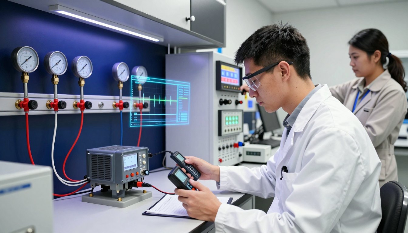
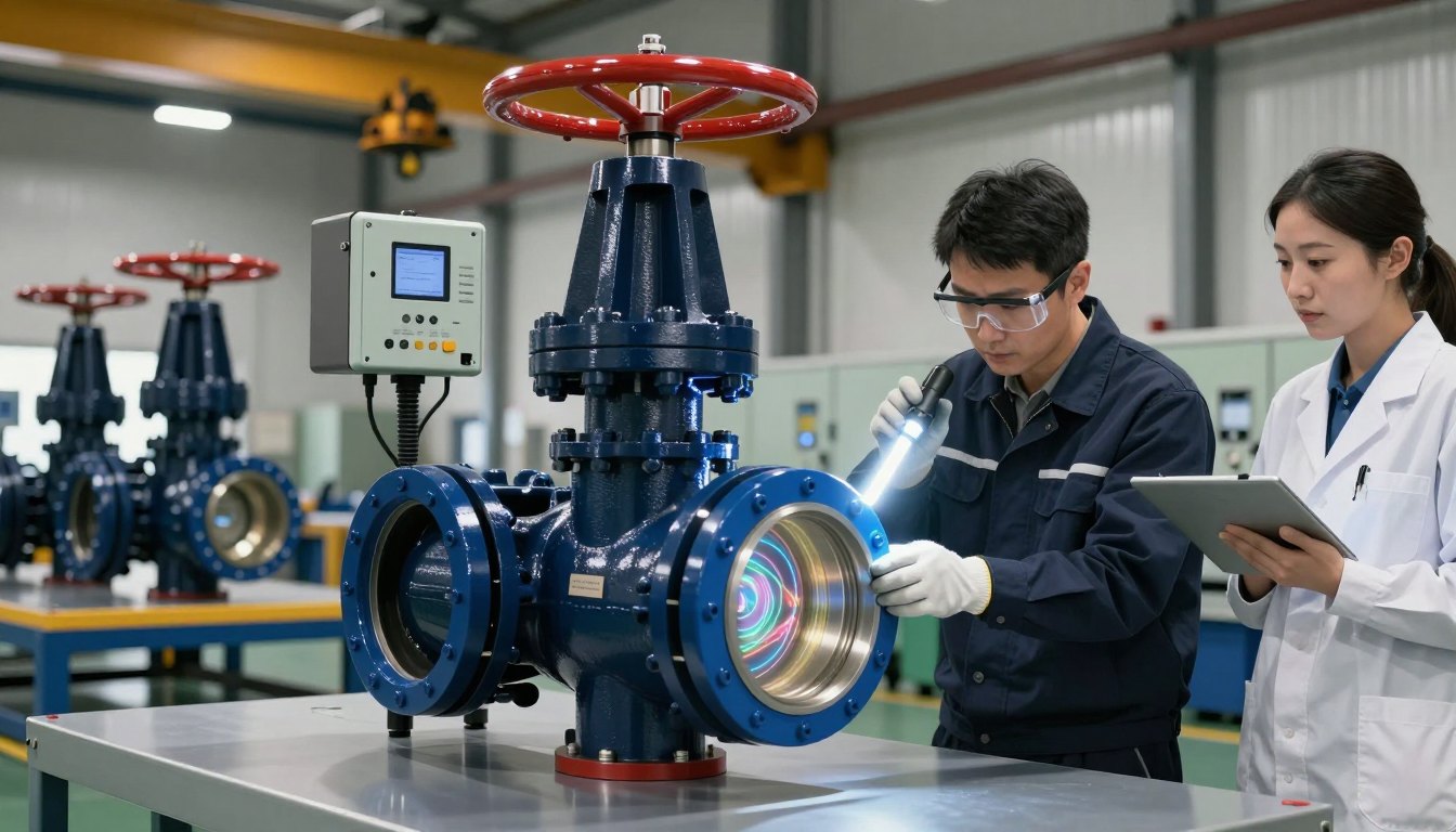
Assessment includes a written examination with valve sizing calculations and a practical session in which candidates inspect and stroke-test a control valve with a smart positioner and evaluate its performance in a live training loop. Practical sessions take place at ASEEE-approved training centers.
Successful candidates are awarded the ASEEE competency certificate, issued with a unique certificate ID that employers and clients can verify online through Certificate Check. ASEEE recommends recertification every 3 years to keep competence aligned with current standards, equipment and site practice.